My partner, Beth, asked me if I could make her a Theremin. So I have. It’s called the Betheremin.
A Theremin is a musical instrument, which changes pitch and/or volume as you bring your hand close to it’s antenna(e). The way this works is by your hand influencing the capacitance of a resonator circuit, changing the frequency at which it oscillates. This difference in frequency creates a “beat” frequency against a reference oscillator, which can then be used to create an audible frequency or control a Voltage Controlled Amplifier.
This is a fairly complicated thing to build — and I didn’t have an awful lot of time, so I went for a more basic design which controls pitch only. I borrowed the circuit from Harrison Instruments “Minimum Theremin” which I have used before (from a kit). It’s a clever design which uses CMOS logic inverters to run the oscillators, and provides adjustment by tweaking the supply voltage. There’s a full explanation of how the circuit works on the Harrison Instruments website.
The first step for me was to transcribe the circuit into CAD format, and at the same time picking appropriate parts to do the job. In a bit of a change from my usual, I decided to source all the parts from Rapid Electronics. It ended up being quite a bit cheaper in the end than Farnell or Mouser, since the components are all pretty common and uninteresting! The BOM ended up looking like this:
| Designation | Description | Part | Order Code | Qty |
|---|---|---|---|---|
| Batt | PP3 battery clip | 1 X PP3 PCB Battery Holder | 18-2990 | 1 |
| C1, C9 | 100pF | 100pf 2.5mm Npo Ceramic Capacitor | 08-0940 | 2 |
| C2, C4 | 0.01uF | 10nf 2.5mm X7r Dielect Ceramic Capacitor | 08-1000 | 2 |
| C3 | 0.1uF | 100nf 2.5mm Y5v Dielect Ceramic Capacitor | 08-0275 | 1 |
| C5, C6, C7, C8 | 10uF pol | Forever 85°C 10U 25V Radial Lead Aluminium Electrolytic Capacitor | 11-0220 | 4 |
| CR1, CR3 | 1N4148 | 1N4148 Silicon Diode 150mA 75V DO-35 | 51-0100 | 2 |
| CR2 | 1N4004 | 1n4004 1a 400v Silicon Rectifier Diode | 47-3136 | 1 |
| Enclosure | Hammond ABS Enclosure Multipurpose Translucent Blue (121 x 66 x 40mm) | 30-3779 | 1 | |
| JACK | 6.35mm jack | 2 Pole PCB Standard Jack Socket | 20-1390 | |
| ONLED1, ONLED2 | White LEDs | 3mm Warm White LED 750mcd | 55-2228 | 2 |
| PITCH-CTRL | 1K Pot | 1K 16mm Linear Potentiometer | 65-0705 | 1 |
| R1, R11, R4 | 270k | 270K 0805 1% Chip Resistor – Pack of 100 | 72-1025 | 3 |
| R3, R12, R5 | 22k | 22K 0805 1% Chip Resistor – Pack of 100 | 72-0907 | 3 |
| R2, R8,R10, R9 | 27k | 27K 0805 1% Chip Resistor – Pack of 100 | 72-0917 | 4 |
| R6 | 100R | 100R 0805 1% Chip Resistor – Pack of 100 | 72-0590 | 1 |
| R7 | 470R | 470R 0805 1% Chip Resistor – Pack of 100 | 72-0667 | 1 |
| RV1 | 10k preset pot | 3306W-1-103 10K ±25% 6 mm Bourns Vertical Cermet Trimmer Potentiometer | 67-0642 | 1 |
| PCB screws | Pozi Countersunk Self-Tapping Screws No.4 9.5mm Pack Of 100 | 33-3415 | 1 | |
| SW1 | Power switch | Spdt R/a PCB Slide Switch | 76-0271 | 1 |
| U1,U2 | CD4069UBE | 4069ub Hex Inverters | 83-0398 | 2 |
| US1 US2 | DIL socket | Tube of 34 14pin DIL Socket, Narrow7.62mm Without Central Support | 22-0108 | 1 |
| VR1 | LP2950ACZ-5.0 | Lp2950cz-5 Micropower Regulator. | 82-0680 | 1 |
| KNOB | 16mm knob | Re’an 16mm Soft Touch Knob with White Pointer | 32-0470 | 1 |
| ANTENNA FASTENING | Spacer – Nickel Plated Brass – 5.5mm AF Female To Female- M3 x 10.0mm – Single | 49-0747 | 1 | |
| ANTENNA FASTENING | Pozi Pan Head Machine Screws BZP M3 6mm Pack Of 100 | 33-2300 | 1 | |
| ANTENNA FASTENING | Steel Washers BZP M3 Pack Of 100 | 33-1760 | 1 | |
| PCB SPACERS | Pack 25 6mm Nylon Spacers | 33-3634 | 1 |
Total cost, £18.04.
I decided to go for 0805 resistors, simply because it saved on space and they were cheaper (as well as having some in stock already).
The enclosure is a nice translucent blue Hammond box, which lit up with the white LEDs will look awesome. I designed the PCB so it’d fit into the box and use the mounting posts already provided.
I decided that I wanted all of the parts of this project to be mounted onto the PCB — including all of the connectors, switches, pots and battery boxes. The PCB would be mounted to the lid of the box, rather than inside the body, using nylon standoffs to give enough space between the PCB and the lid to fit the PITCH ZERO potentiometer.
For mounting the antenna, I used a hex profile spacer and a machine head screw, sandwiching the pad and providing a screw thread flush with the lid of the box (after drilling a hole). The antenna I got from eBay, with a M3 standard thread. This part is the main problematic part to source — I’ve yet to find someone who sells telescopic antennae with screw thread ends in any volume, or any “standard” antenna. I guess there’s not so much of a need for these these days — perhaps a better solution would be a “rubber duck” antenna with SMA connector or similar — but those connectors are quite expensive and I wouldn’t be taking advantage of the benefits of coaxial barrels.
After many hours of careful routing, tweaking and massaging, I had a PCB ready to go:
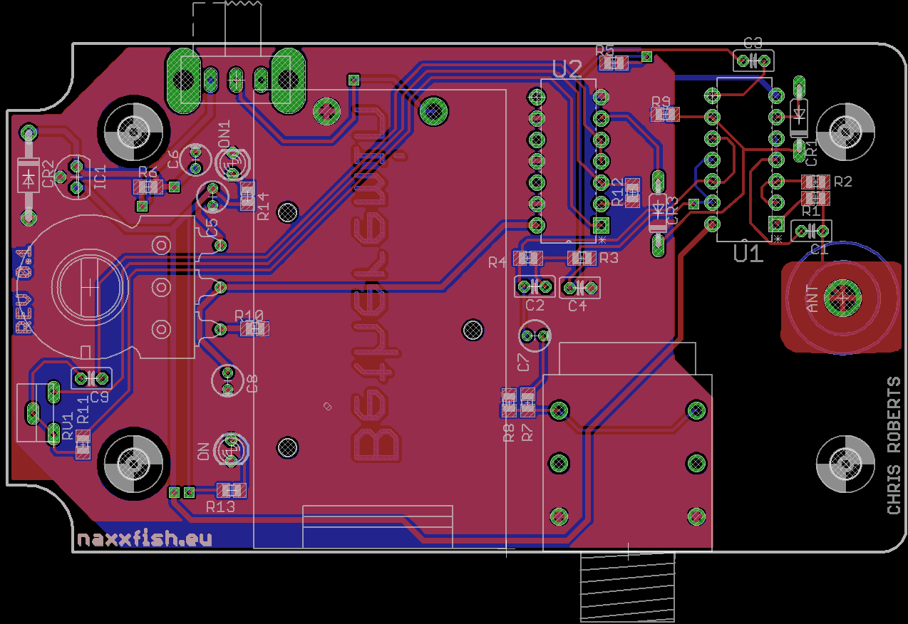
The final PCB layout in KiCAD
There’s a power slide switch at the top side, which looks like it’s going to interfere with the battery box! But, I thought, why not put that on the other side of the board, since it’ll work exactly the same. Remember that ….
The “bottom” side of the board, is actually the side that’s going to be facing upwards in the box. This means all the components are on the open side of the board, except the LEDs and the potentiometer. I didn’t want there to be silkscreen on the side facing upwards, so I put the markings (the Betheremin text) in the copper layer, and peeled back the solder mask — which once the board has been through the gold flashing process gives a nice gold text 🙂
So, PCB design, I needed to get them produced. I had a few options, but I had previously used BatchPCB to great success. Thus, I decided to try out it’s successor, OSHPark. They accept Eagle files (no faffing around with Gerbers, yay!) and they give you a great automated preview when you upload your design files. I was kept informed throughout the process, from sending them to the fab house to sending the boards back to me. The price was very reasonable, and considering the boards were shipped to me in the UK from the USA, came pretty quickly. Also the packaging, like the PCBs, is awesomely purple 🙂 I will definitely be using them again!
This is what I was shipped from OSHPark:
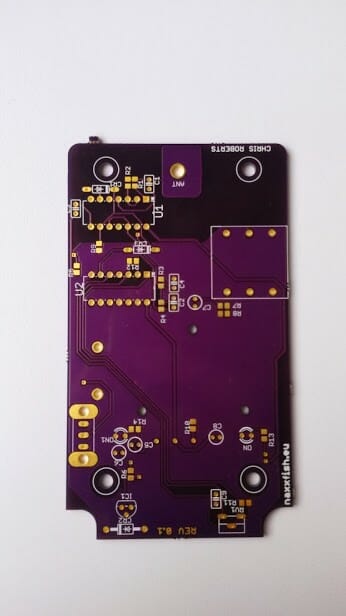
Beautiful purple PCB goodness
Gorgeous! I’m very pleased with the quality. The routing is very smooth, the soldermask is very consistent. The registration on the silkscreen was a little off, but that’s to be expected really.
After a little filing around the edges to make up for the snap sprues, and the slightly tight tolerances around the curved corners, it fit into the box perfectly!
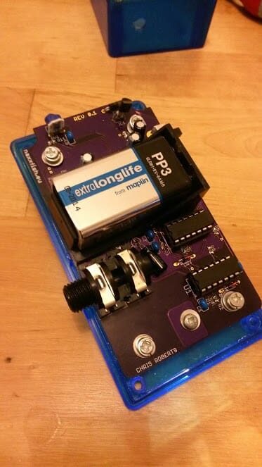
Some soldering later:
In this side shot, you can see how the hex-spacer works to let you screw the antenna into the lid, and where the pot is attached to the board on it’s back.
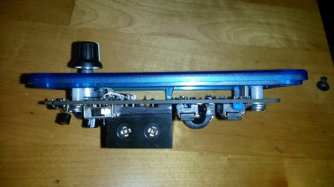
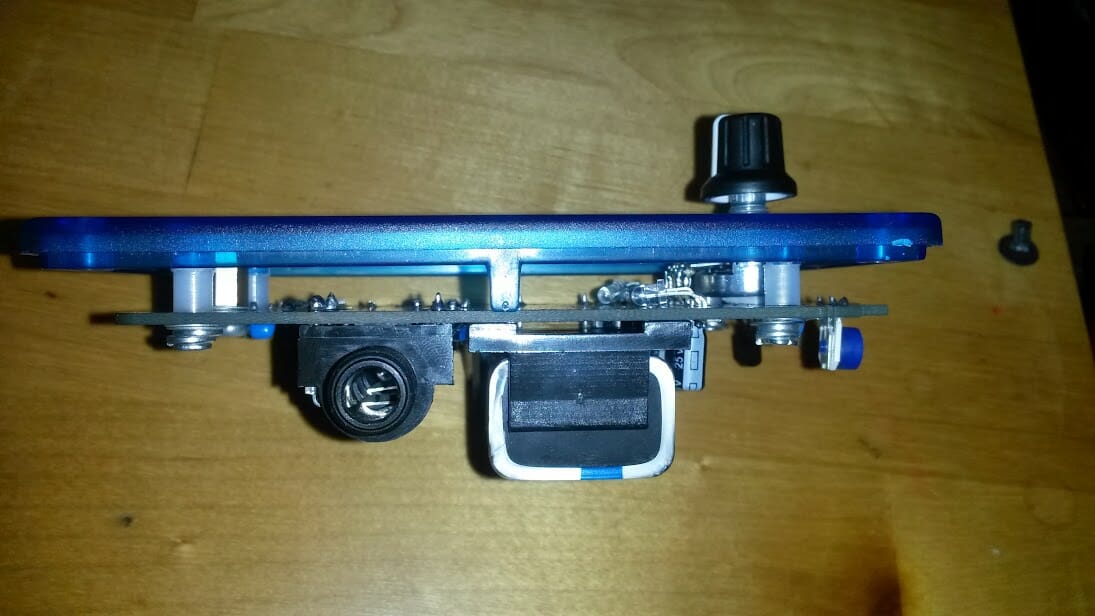
The pot was secured to the PCB using normal self adhesive pads — mainly just to stop it putting strain on the pads. The shaft on the pot could do with being a little shorter — so that the knob doesn’t float quite so far away from the panel.
Note the slide switch. I put it on the wrong side … doh! It interfered with the battery box a little, which — rather than putting the switch on the other side of the board — I filed the battery box a little to make it fit. Doh!
The LEDs point up the board, allowing the solder connections to reflect the light to produce an interesting pattern when the device is on.
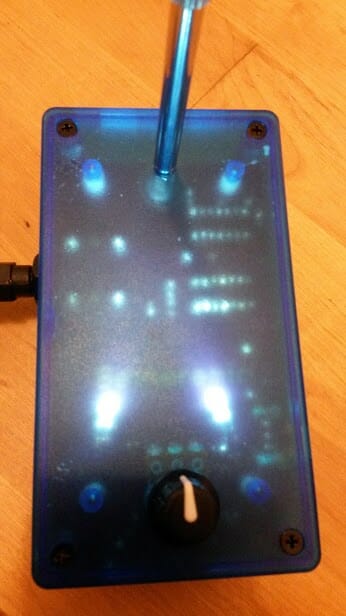
Overall, it looks like this:

After some fairly tweaky calibration you can control the pitch from about 12 inches away. If you are grounded well, then this works even better and you get more range. It produces a mostly sawy sine wave (pretty much an RC oscillator sort of curve really, not surprisingly). I did try to put a RC low pass filter on the output (by putting a 1uF cap between the output and ground) to see if that’d make the output more siney — but unfortunately it did attenuate the output rather significantly at the frequencies we were interested in (between 0 and 1500Hz ish).
Revisions
In REV 0.2, if I make another one, some things to note:
- Put the slide switch on the right side :p
- Make RV1, the calibration trim pot, multiturn as the single turn one was very tweaky to adjust
- Make the thermals thinner and the pads bigger (desoldering is a pain otherwise!)
- Increase the spacing between the 0805 resistors
- Don’t put anything under the battery box 🙂
- Make the holes to mount the battery box big enough to clear a No 3. self tapping screw, so the box can be secured to the PCB properly.
- Increase the tolerances on the PCB borders so it’ll fit without needing filing!
Future enhancements:
- Put a proper amplifier on the output, with gain control
- Provide a volume control
- Break out PWM output to control other things.
- Generate MIDI/OSC messages over USB?!
Overall this was quite a fun little project, and something I’ve not done for quite some time! And immensely satisfying that not only is it complete and works well, but also that it’s going to be used productively!